Back to the product list

FLEX Series - Refrigerated Air Dryers 75 to 2000 scfm

DRYERS - COMPRESSED AIR / REFRIGERATED COMPRESSED AIR DRYERS

FLEX Series Sustainable Energy Saving Solution

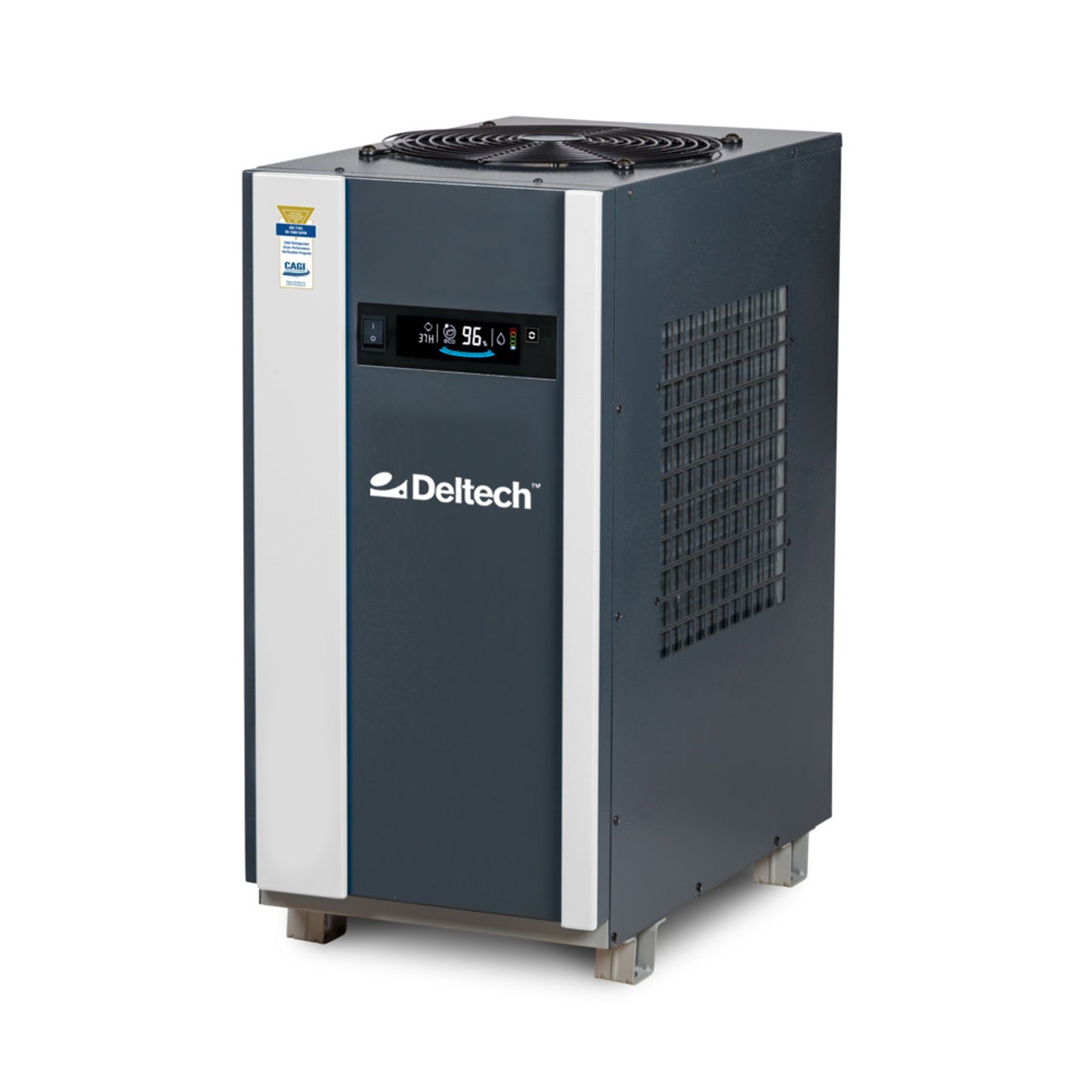
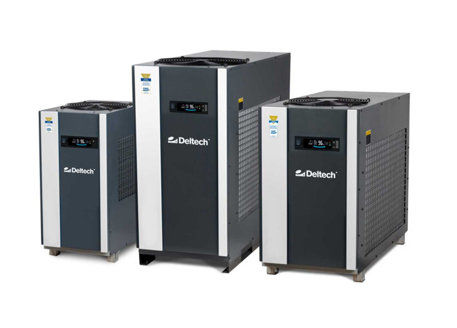
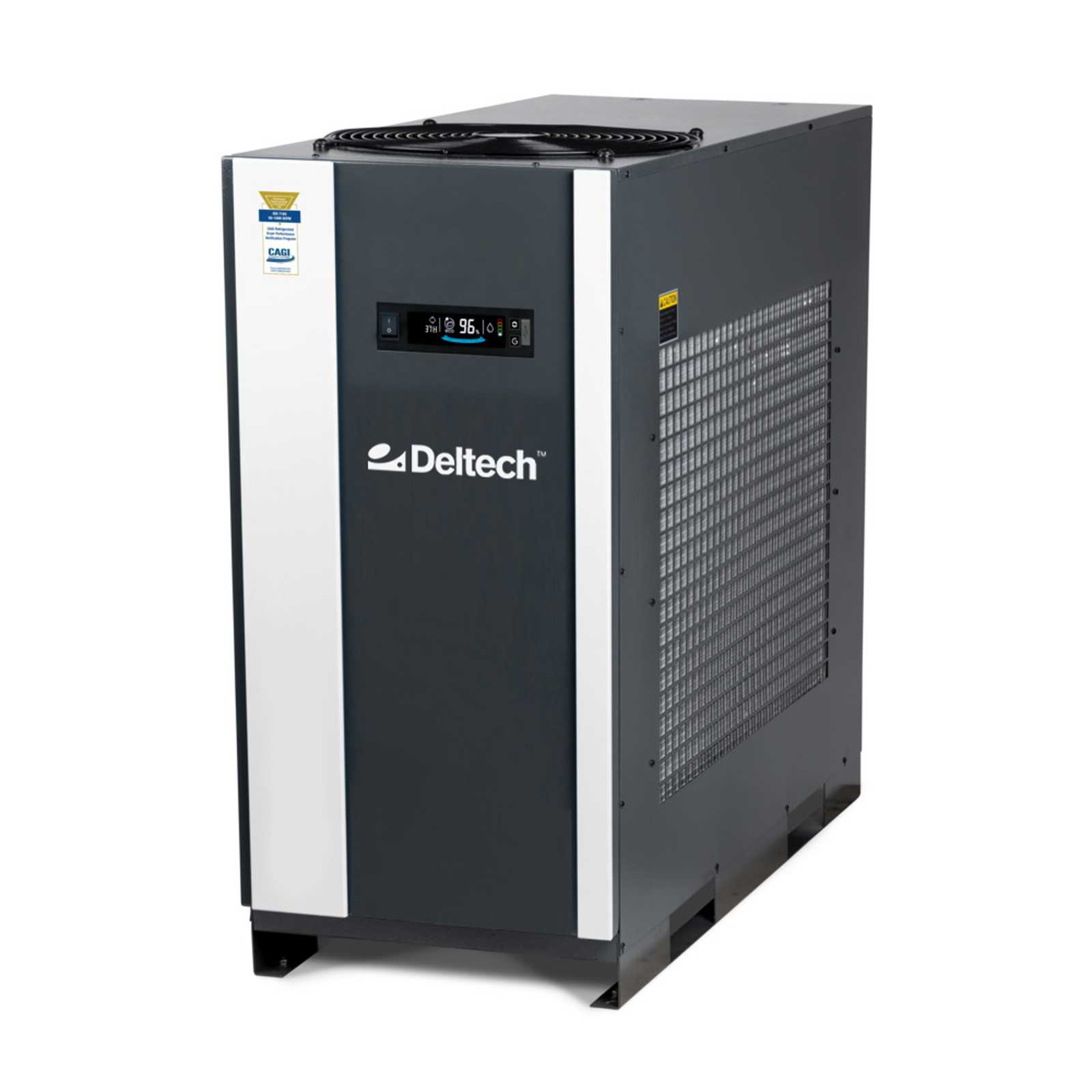
Energy Saving Sustainability

The FLEX Series lowers air system power costs and improves productivity by matching power consumption to compressed air demand.

In a typical manufacturing facility, up to 30% of electricity consumed is for generating and treating compressed air. To reduce total cost of operation and qualify for utility company incentive programs, proper air treatment equipment selection and application is required.

Load Matching Performance

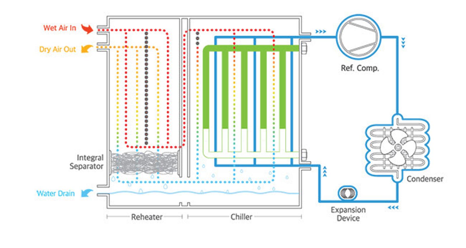
Compressed air load profiles in most manufacturing facilities fluctuate. The FLEX Series provides cost-effective energy savings by matching electrical power consumed in direct proportion to air demand. Linear load matching is achieved from 0% up to 100% demand.

Non-cycling dryers operate with the refrigeration compressor running continuously, regardless of inlet load conditions. Minimal energy savings are realized from 100% down to 0% inlet air load.

Linear Energy Savings

FLEX Series dryers automatically cycle (on /off) the refrigeration compressor in response to inlet load conditions. As the inlet air load is reduced, the power requirement to dry the air is matched in proportion to the demand. For example, at 60% inlet air load, a non-cycling dryer consumes 96% of the full load power consumption, a 4% energy savings. By comparison, at 60% inlet air load, the FLEX Series consumes only 60% of the full load power, a 40% energy savings.

How It Works

  1.  The FLEX Series utilizes a phase change (PCM) heat transfer medium between the refrigeration and compressed air circuits that serves as a reservoir for thermal storage. 

  2. The thermal reservoir is comprised of a 3-in-1 heat exchanger (patent pending) filled with a phase change material that efficiently transfers heat energy through a “change of state”.

    Phase Change: changing from liquid to solid back to liquid in a continuous cycle

  3. The refrigeration circuit operates to cool down the PCM until it forms into a solid at which time the refrigeration system cycles off. 

  4. As the compressed air enters the PCM to air section of the heat exchanger, the PCM media absorbs heat for the airstream and begins to melt the PCM media at a constant temperature. 

  5. When most of the PCM media has turned to liquid the refrigeration system cycles on to again cool down the PCM media turning it back into a solid. 

  6. This cycle repeats as required to meet the corresponding compressed air load on the FLEX dryer. 
flex-series-flow.jpg

FLEX Series Models for North America

Dryer
Model

Inlet Flow

Pressure Drop

Voltages

Inlet/Outlet
Connections

Operating Power

SCFM

NM3/H

PSI

IN

KW

DFX 1.1

75

127

2.9

115/1/60

NPT 1"

0.54

DFX 1.2

100

170

3.0

115/1/60

NPT 1"

0.62

DFX 1.5-1

150

255

3.6

115/1/60

NPT 2"

1.04

DFX 2.1-4

200

340

2.2

460/3/60

NPT 2"

1.26

DFX 3.1

300

509

3.6

460/3/60

NPT 2"

1.99

DFX 4.5

450

765

3.0

460/3/60

NPT 2"

3.23

DFX 5.5

550

935

3.0

460/3/60

NPT 2"

3.42

DFX 8.1

800

1300

3.7

460/3/60

FLG 3"

4.30

DFX 10.1

1000

1700

5.0

460/3/60

FLG 3"

5.84

DFX 12.5

1250

2150

4.6

460/3/60

FLG 4"

7.60

DFX 15.1

1500

2550

3.9

460/3/60

FLG 4"

9.00

DFX 20.1

2000

3400

3.1

460/3/60

FLG 4"

10.00

Performance data presented in accordance with ISO 7183 (Option A2) conditions: 100°F inlet temperature, 100°F ambient temperature and 100 psig conditions.


FLEX Series Models for EMEA

Dryer
Model

Inlet Flow

Pressure Drop

Voltages

Inlet/Outlet
Connections

Operating Power

SCFM

M3/H

BAR

IN

KW

DFX 1.1

75

127

0.20

230/1/50

 1"

0.43

DFX 1.2

100

170

0.21

230/1/50

 1"

0.43

DFX 1.5

150

255

0.25

230/1/50

 2"

0.59

DFX 2.1

200

340

0.15

230/1/50

 2"

0.85

DFX 3.1

300

509

0.25

230/1/50

 2"

1.30

DFX 4.1

400

680

0.17

230/1/50

 2"

1.66

DFX 5.5

550

935

0.20

230/1/50

 2"

2.00

Flex Series Models

Dryer Model

Dimensions

Approx Weight

H

W

D

IN

MM

IN

MM

IN

MM

LB

KG

DFX 1.1

30

751

14

363

24

603

120

54.5

DFX 1.2

28

711

14

363

31

781

147

66.5

DFX 1.5-1

30

761

18

443

36

901

203

92

DFX 2.1-4

30

761

18

443

38

961

244

111

DFX 3.1

36

911

19

493

44

1111

324

147

DFX 4.5

41

1032

20

494

49

1253

366

166

DFX 5.5

41

1032

20

494

49

1253

396

180

DFX 8.1

59

1488

32

800

59

1494

1056

476

DFX 10.1

59

1488

34

850

62

1572

1211

549

DFX 12.5

59

1488

39

1000

62

1572

1537

697

Performance data presented in accordance with ISO 7183 (Option A2) conditions: 100°F inlet temperature, 100°F ambient temperature and 100 psig conditions.